Земля на регуляторах.
Почему нужно подключать сигнальный земляной провод, и почему “а у меня и без него работает”.

I do that type of scope measurement and we have a saying, “ground is not ground is not ground”. Meaning there is ALWAYS a Potential difference between two points if any current flows (Ohm Law: E = I*R).
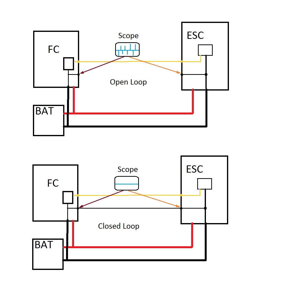
In the first case in the above diagrams, The ESC is switching high current and drawing that current through the power leads. The current flow causes a Voltage drop on both the Red and Black wires and also ‘kick-back’ (LC) causing spikes. The Scope then sees this Voltage drop as in the diagram. The ESC sees this Voltage drop as a change in the FC signal. If the drop is enough then a Logic high signal from the FC will look like a Logic low signal and the ESC takes this as a PULSE width change (motor Speed change).
In the second diagram, there is a NON-current carry ground wire that the maintains the reference to the FC’s signal so the power wire Voltage drops and spikes do not cause False logic levels.
If the Signal amplitude is large enough and the system ‘ground’ noise is not too high then a single wire (FC to ESC) will work. This was the case in the old MultiWii FC that used a 5V processor and signals to the ESCs.
When the STM32, 3.3V processors started to be used many started having problems with the signal to the ESCs since the signal level is now a good bit smaller (3.3V instead of 5V). The cure is to also connect a ground wire from the FC to the ESC.
What this does is maintain the signal Voltage difference to the ESC.
This lead to many arguments about ground loops (multiple paths for return current).
Part of the reason is that there are many factors that come in play so on some builds a single FC to ESC wire work perfectly whereas in another build a single wire causes signal problems.
If you are unsure then it is safer to run both a signal and ground wire from the FC to the ESCs.