Activity
Nick Shl , please post a file hex here if you can share . thanks
hello everyone
i used esc trackstar 150a sensorless , i having difficult , it only sound BEEP , BEEP , not thrust , servo work well. I still can setup by card program ,
without sound Beep , beep … it doesn’t do anything. What is problem ?
anyone having trouble same me 😅😮

here is confuse between FLYSKY ( A7105 ) and FRSKY (C2500 ) .That is code of midelic on Rcgroup
for receiver , i used a nrf24l01 + LNA … result very good, over 700m.

if it connected a anten board 2.4ghz , it will very stable and far
someone convert code er9x to use for Lcd 5110 ?
anyone used firmware er9x with a lcd 5110 ?
Купил себе передатчик dx.com/…/wltoys-wl-r7-large-left-right-hand-adjust… . Вещь вроде не плохая: удобный, механизмы ручек без заметных люфтов, потенциометры там стоят маленькие в квадратном корпусе, про ресурс не знаю. Есть механический переключатель ручки газа на левую сторону и на правую. Триммеры электронные, потенциометры ручек к плате подключены через разъёмы. Справа на верхней панели 4 кнопки, центр не нажимается. Впереди слева и справа есть по кнопке. Внутри места много. ВЧ часть собрана на A7105 с усилителем 1112. По слухам это аппаратно совместимо с приёмниками НК 2-ой версии. Дисплей специальный под вертолёт. Как донор для переделки вполне хорошая вещь!
I have it
but its monitor only communication 7 wire. LED+ LED - CS ,WR,DATA,GND ,VDD ?
And Do you make A7105 external ? or add write code for át128 ?

hello NICK_shl
can you post here full your program ? I like to use a lcd KST1080 .
OK, i done with Version Condevision v2.
Although a litte difficult , but everything become good
Now, i try insert a Nrf24l01
hello Msv
what did you use verision Condevision ? I have a few error when i complie file Hex because code limit exceed 3kb.
i use Condevision Verison v1
Приемник у меня используется в ретрансляторе nrf24l01->RFM22b. К сожалению схемы нет, там обычное соединение по ДШ к мега8.
uhmm. i will try upgrade nrf24l01 .this is great if tx have both " output PPM and output Nrf24l01 " .And a new version for TX car in next time
Моя последняя прошивка (не публиковал, но могу выслать всем желающим) поддерживает именно эти модули. Эта прошивка под серьезно измененную схему.
Изменения в основном сделаны для удобства разводки.
Модуль используется только для связи с ретранслятором в котором RFM22b c бустером (LRS).
Впечатления о работе модуля неоднозначные… Иногда уверенный прием >50м, а иной раз рядом начинают сыпаться куча дропов.
Думаю еще поэксперементировать с расположением модулей, возможно с антеннами, может получится добиться более-менее устойчивого канала.
Hi Msv
you can show me RX nrf24l01 that you use ? I try change code to suitable RX of Denn . Because when use lcd nokia 5510, atmega128 still free Pin.

hello Д. Заточник and RW9UAO
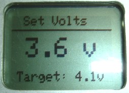
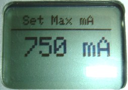
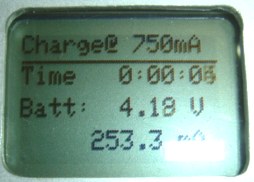
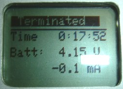
Program and sofware build with a Arduino Uno and it’s still continues develop .
a few features as :
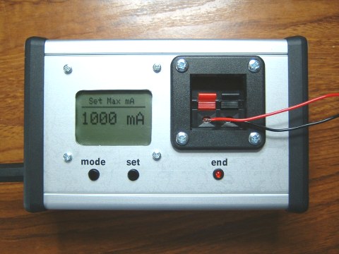
min 100ma and max 1000ma
setup Volt
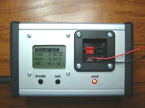
display Timer charge
currently , charge 1s lipo,lithium…but can develop to 6s lipo and blance for each cell
I will post all here new verision then project complete
hello Nick_scl
TX can setup program ''slow servo ‘’ for any channel ? i want to use for a FLAP , so have to control speed servo .
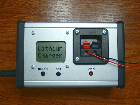
here is project DIY a box charge lithium, but i think it can use for battery lipo if change little code . 😎
ok, all we will build it with a Arduino .😉 sorry because English here .
www.vwlowen.co.uk/arduino/charger/charger.htm


here is code create sound engine by PICAXE : Lol:
someone this do with microcontrol pic or avr or arduino ???
hello Guy
can you show some picture ? Wonderful project
i am sorry when use english here because i don’t know language Russia. I have to use google translate and guess mean
here is all what i want to say :
deviationtx.com/forum/protocol-development

wonderful Olympic Shochi : Lol:: Lol:: Lol:
hello dollop
can build a protocol same Devo ? Mean is add some modul 2.4ghz nrf24l01, a7105,cc2500…all three modul had protocol ( Flysky, skyvatec, V202… ) .we will load them in atmga128 , and use them if need.
that only my idea
The firmware for this project is not the same as for turnigy 9x or flysky 9x.
But if you want to use this software on the turnigy 9x hardware you may change defines in the file def.h according to the schematic. Than it may be useful for you to check another thread
The firmware described here is capable to store 7 models in memory (it uses Mega128 built in eeprom). You need unmodified firmware for your 5110 display. The latest version is 1.9.1 For this firmware you may use any hardware listed here
There is another firmware that is designed to use external eeprom chip. In this case you’ll be able to store up to 100 models with 24С512.
I want to say it once more:
- If you want to create your own TX the fastest and the easiest way is to buy the turnigy 9x main board, apply your sticks and buttons.
- If you want to apply more soldering, more DIY 😃 and to create your TX from scratch than this project is your chioce.
As a person who uses both systems I may say that er9x has more complicated menu, it is also fully customized and you are able to implement any control logic, while this system is rather powerful, easy to understand and use.
very clear , thank a lot
i choice DIY , it is interesting
Cheer
i wonder ,firmware and schematic of this project how firmware flysky 9ch ?
and firmware of this project can save how many program ? because i use for some airplan
Sorry ,because i am waiting order chip 128 ,lcd5110 ,so i am not yet make this circuit
Use firmware and hardware here is right ?
sites.google.com/site/…/nokia3310_unoriginal

Okey ,wonderful ,
i will buy a lcd 5110 to upgrade for my TX with project avr 128
here also project Diy TX 6ch use arduino + lcd 5110,it is simply
www.rcgroups.com/forums/showthread.php?t=1817699&p…

hey dollop
can use Lcd nokia 5110. but i see input 5110 is diffirent 3310.
and i think have to change code , do you try ?
monitor 5110 is popular than 3310.
hello Msv
this project can monitor Nokia 5110 to replace for NOkia 3310 ?
Denn
i am sorry because i slow understand.
All thing is ok. i understood
thank a lot for your Project
happy chismast and new year
Cheer
failsafe save to EEPROM when you disconnect Ground ( - )
Denn
Ok,failsafe for Electric rc. wonderful .
And now, failsafe for Rc car use engine nito ?
It is like this :
You can program all channel for failsafe self. You must stand all stick into failsafe position, close and open input failsafe to ground (-).
pin failsafe is 32, i connect to Ground ( - ) . Led will OFF, however it still don’t change when lost signal .
So,i have to change code ? Is code here ?
void FileSafe(void) // ìíîãîêðàòíàÿ îøèáêà ïðè¸ìà
{
Kanal[0]=E_F_Kanal[0];
Kanal[1]=E_F_Kanal[1];
Kanal[2]=E_F_Kanal[2];
Kanal[3]=E_F_Kanal[3];
Kanal[4]=E_F_Kanal[4];
Kanal[5]=E_F_Kanal[5];
Kanal[6]=E_F_Kanal[6];
Kanal[7]=E_F_Kanal[7];}
void Safe(void) // çàïèñü
{
F_Kanal[0]=Kanal[0];
F_Kanal[1]=Kanal[1];
F_Kanal[2]=Kanal[2];
F_Kanal[3]=Kanal[3];
F_Kanal[4]=Kanal[4];
F_Kanal[5]=Kanal[5];
F_Kanal[6]=Kanal[6];
F_Kanal[7]=Kanal[7];
FS_On=1;}
void Safe1(void) // çàïèñü
{
E_F_Kanal[0]=F_Kanal[0];
E_F_Kanal[1]=F_Kanal[1];
E_F_Kanal[2]=F_Kanal[2];
E_F_Kanal[3]=F_Kanal[3];
E_F_Kanal[4]=F_Kanal[4];
E_F_Kanal[5]=F_Kanal[5];
E_F_Kanal[6]=F_Kanal[6];
E_F_Kanal[7]=F_Kanal[7];}
I not understand this. When signal is lost , failsafe is work over 1-2 s. You need to program failsafe .
Mean is this :
Example : signal max ESC is 1.9ms and Stop is 1.0ms .
When runing signal max 1.9ms then lost signal , Your RX keep signal output is 1.9ms instead return first signal .So ESC still run max . Can lost airplan or Crack .
So , add fuction Failsafe all Output (0 ->7 ) when lost signal
Channel 1…1.5ms
channel 2… 1.5ms
channel 3… 1.0ms ( throtle )
channel 4…1.5ms
…
…
channel 8…1.5ms
i think it is very importand.
Cheer.
Why?
Denn
it is work very good . However, when lost signal from TX , RX is still keep final signal . ???
So ,If you move Max stick and then lost signal , motor will run Max ,it can not stop .: O
Your RX just have final error is when lost signal , should returned at the first signal instead of keep final signal


If TX have 2 channels PPM, TX nRF will send 32 bytes with 8 channels, but 3…8 channels is wrong. TX will transmit only 1 frequency - F1. I not know about IRQ and CRQ.
thanks Denn
mean is if i want use any channel ,i have to change code to suitable amount channel : Không chắc chắn:
EX , 2 channel is change code TX ,RX for 2 channel
pin 32 atmega8 of RX is input for filesafe. it connect to ground and disconnect for write filesafe.
ok Denn , add a few question to i can clear .
If i use tx create PPM is 2 channel ( tx of car ) , Circuit can work with 2 signal output ? Or only work with PPM 8 channel
And Pin IRQ my nrf24l01 name is CRQ , Is it difference ?
You can post few picture file Layout of TX ,RX by file PDF ? what are you use software to draw ?
thank a lot .
Cheer
hello Denn
i can not understand why it do not work .
project Nrf24l01 , led only flash, it can stop then turn off . have you a shematic complete ? where is pin 32 atmega8 of RX connect ?
Hi Denn
here is layout TX RX ,i use eagle .😉

yes,i know it is work 8ch
but problem is have not signal output from RX
Led off, i use ppm from TX flysky 9ch .
if you can post a video , or some picture i think i will see it work how
thanks
hello Denn
i did circuit same you, but it do not work, have not signal from Pin atmega8 of RX.(